A new process for modeling fuel tanks is delivering greater design accuracy and saving automotive supplier VITEC up to 40 percent in product development time.
VITEC produces plastic fuel storage and delivery systems for automotive manufacturers, including General Motors, DaimlerChrysler and Harley-Davidson. Like most suppliers, VITEC uses volume and grade-line studies to assess manufacturability and functional performance of its designs before production.
he studies require variable thickness information that is not available without the manufactured part. In the past, VITEC has conducted simulations based on an average thickness value assigned throughout the tank shell. But such estimates leave room for errors that can add to production time and lead to retooling costs.
VITEC’s new process compares simulations from CAD data with models derived from scanned physical parts to ensure accurate thickness measurements. The process starts by simulating the blow-molding process used for producing fuel tanks.
Extrusion blow molding is done with a plastic tube (called a parison) that is heated until it reaches a molten state and then forced through a die. Synchronized motion of the die’s core determines the thickness values on the parison.
“Parison inflation forces the plastic against the mold cavity walls to end up with the tank’s final shape,” says Dr. Karim Amellal, product development manager at VITEC. Once cooled, variable thickness of the manufactured part can be measured at various locations.
VITEC’s new methodology simulates the entire blow-molding process, automatically calculates thicknesses, and reconciles the CAD model with the actual manufactured part.
“With the introduction of blow molding simulation technology, one is able to anticipate any process and design issues and predict variable tank wall thickness levels before manufacturing ever begins,” Amellal says.
Greater Accuracy in Less Time
VITEC’s process begins with a customer providing the envelope boundaries in which the fuel tank will reside in the vehicle. These boundaries dictate the tank’s shape. VITEC loads the boundary data into Unigraphics or CATIA CAD files of the fuel tank shell.
The part files are exported from the CAD system as stereolithography (STL) files. Some of the files are imported into MSC.Software’s Patran software, which generates a finite-element mesh of the outer surface of the fuel tank. Others are imported into BlowView simulation software, where they are converted into Patran files to be used by the analysis solver BlowSim to calculate thickness values on the inflated parison. The parison thickness results are then mapped onto the meshed outer surface of the fuel tank.
Predicted results of the extrusion blow molding process for a tank design are obtained from BlowSim and then processed within Patran. The inner solid is generated within Patran by offsetting the thickness values from the outer surface.
“The blow-molding simulation analysis provides optimum process conditions to achieve uniform tank thickness distribution,” Amellal says. “The results save tooling and material costs by assessing all process and design issues at the initial stages of product development, minimizing the number of iterations.”
The Patran STL files for the inner and outer surfaces are imported into Geomagic Design X (formerly Studio) software, which is used by manufacturers for mass production of customized devices, build-to-order manufacturing, and automatic re-creation of physical parts and molds.
Bridging Physical and Digital
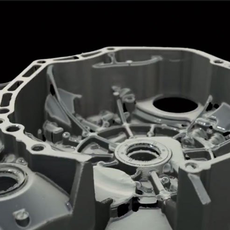
VITEC uses an optical scanning system to digitize the outside surfaces of a fuel tank shell taken from the manufacturing floor. The point-cloud data from the scanner is brought into Geomagic Design X for surface enhancement and modeling. Surface repairs and hole filling are done automatically within Geomagic Design X to create a closed-volume polygon.
The shell sample is then cut in half and the inside surfaces scanned. The outer surfaces on the shell halves are also scanned to obtain datum plane references. After scanning, the two half-tank point clouds are imported into Geomagic Design X. The software automatically merges the two halves using a best-fit alignment tool.
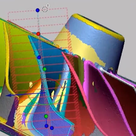
Geomagic Studio enables VITEC to do a 3D comparison between the BlowSim-derived Patran models and the models generated from the scans of the actual fuel tank. This enables VITEC to validate the theoretical predictions of wall thickness obtained from BlowSim.
The effects of warpage can also be modeled in Geomagic Design X. When cutting the tank shell, the plastic walls warp as a result of frozen-in residual stresses during the cooling stage of the blow molding process. Geomagic Design X performs a 3D comparison to compute the negative and positive tank wall deformations resulting from the warping.
Validation Through Graphical Comparison
In addition to the visual comparisons of thickness and warpage made within Geomagic Design X, VITEC compares measurement values obtained from the physical part to those from the simulated model. This is done by VITEC’s quality assurance group using Geomagic Control computer-aided inspection software. Geomagic Control automatically aligns and compares measurement data from cross-sections of the physical part with the BlowSim model.
“This validation process is performed to verify the accuracy of simulation results and to make us feel confident about future predictions on virtual parts,” Amellal says.
Computer-aided inspection replaces a process that involved measuring the wall thickness levels using an ultrasound technique. The technique requires that a grid be applied to the tank surfaces; thickness values are measured at the grid cell corners. A coordinate measurement machine (CMM) is also used to measure and verify dimensional integrity of the fuel tank.
Amellal says the combination of the scanner and Geomagic Control provide greater speed and accuracy than the ultrasound technique, and could potentially replace the CMM machine as well.
“We think we can use optical scanning and Geomagic Control to potentially reduce product quality inspection time by at least 20 to 30 percent,” Amellal says.
Identifying Issues Before Production
After quality assurance, the model is sent back to VITEC’s product development team, which uses Geomagic Design X for a final 3D comparison between the captured physical part and the BlowSim model. STEP files are exported from Geomagic Design X back to the CAD system, where designs are modified as needed.
The process provides VITEC not only with the variable thickness information needed to perform accurate volume and grade-line studies, but also with a realistic model for vehicle crash simulations.
“Customers don't have to wait anymore for physical tests to evaluate whether a fuel tank will perform in a vehicle environment,” Amellal says. “That is the main reason why these computer simulation technologies are used by VITEC. We can anticipate issues relating to manufacturing, structure or refueling prior to actual production. Cost savings are achieved and customers benefit.”
VITEC performed two studies to verify accuracy of the fuel tank simulation. First, volume studies compared theoretical volumes from the simulation process with the actual volumes of two different gas tanks. Results showed accuracy levels of 99.5 for a small car gas tank and 97.7 percent for a truck tank.
Similarly, studies of height versus volume during tank refueling showed a theoretical filling curve that fit very closely with the actual curve provided from the testing lab.
“This suggests that computer-aided analyses used at VITEC can reduce the cost and time consumed with physical tests tremendously,” Amellal says. “Initial estimates suggest significant cost savings and a reduced product development time of up to 40 percent.”
Setting the Standard with an Automated Tool
Eventually, VITEC hopes to develop an automated simulation tool that can address all customer requirements in terms of fuel tank manufacturability, structural integrity and refueling performance. Relying on commercially available software packages – BlowView, Patran, Geomagic Design X and Control — for internal simulation capabilities is only the first step.
“VITEC plans to develop a methodology to automatically transfer data from one software package to another, and to build an interface that will link all of the internal simulation capabilities,” Amellal says. “The result will be a fully automated simulation tool (FAST) that CAD design engineers can use on a daily basis during the product development stage. That's VITEC’s vision.”