SAM Department (Strömungsmechanikm Akustik und Strömungsmaschinen) relies heavily on 3D Systems Geomagic Design X Software to get the highest quality models.
Since the Wright brothers, advances in aerodynamics have typically come from two places: field testing and the wind tunnel. More recently, a new tool has been added to the toolbox. Computers using Computational Fluid Dynamics (CFD) have become a critical new tool in development and testing of design alternatives. The Department of Mechanical and Process Engineering at The Technical University of Kaiserslautern (www.uni-kl.de) is renowned for its advancement of the study of aerodynamics, improving the efficiency and stability of aircraft and aerospace vehicles in flight. Presently, the University has undertaken a project involving testing of Aerospace structures using all three; test flights, wind tunnel and CFD.
This project uses the complementary discoveries made in the physical flight and wind tunnel, as well as those made in a CFD simulation on the computer. Of course the value of the discoveries in each mode is dependent on the fidelity of the physical model to the computer based model. Any differences in the form of the models could taint the results. To get the highest quality models, the SAM Department (Strömungsmechanikm Akustik und Strömungsmaschinen) relies heavily on 3D Systems software.
No matter what kind of power system is being used for creating thrust, aeronautical engineers must design to optimize the aerodynamic properties of the aircraft. When improving on an existing design, the engineer generally needs to analyze the current aircraft in a CFD simulation by using a watertight polygon model. This model is often made from laser-scans of the physical model (i.e., an existing fuselage, a wind-tunnel model).
Geomagic Design X generates the best-in-class mesh data from scan data, as well as from the CAD model. For physical model conversion: Design X uses its “Mesh Buildup Wizard™” to create a defect-free, watertight mesh automatically by combining multiple scans from many points of view, merging and remeshing the result to yield an optimal mesh for CFD. For CAD models, Design X uses the mesh generator to create a high-quality mesh model from the CAD model.
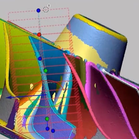
To confirm the created model’s dimensions, Design X’s “Accuracy Analyzer™” provides feedback on the dimensional deviation of the input vs. the output polygon models via a variety of analysis tools (mesh to mesh, mesh to CAD etc).
Any changes made as a result of CFD runs (to optimize its flow, reduce flutter, etc.) must be reflected back into the CAD model. Design X offers two ways to convey the changes made to the polygon model back to CAD. The CAD model can receive NURBS surfaces representing the changed polygon model, i.e., 2G (second generation) modeling. Alternatively, the modeler could use a unique feature of Design X is a function called CAD correct which will reform existing CAD surface to reflect the shape of polygon automatically. However, one limitation of 2G modeling is that these forms are not easily edited or modified in the CAD environment.
If an editable CAD model is the desired result, Design X also offers 3G (third generation) modeling; that is the means to create an editable, parametric CAD model from the polygon model. The result is a native CAD model in NX, Pro Engineer/Creo and Solidworks, including an intact editable history-tree. 3G modeling facilitates feature based parametric editing within the CAD environment, very useful if further changes will result from downstream processes.
The Technical University of Kaiserslautern project is well under way, testing multiple iterations in the CFD environment which uses Design X’s best-in-class polygon model. The results so far have met or exceeded the team’s expectations, and they are identifying new projects for 3D Systems’ software capabilities in the future.