Here’s the challenge: reverse engineer a railroad tamper casting based on 40-year-old drawings that don’t even come close to matching the physical casting. It will be impossible to capture all the surfaces with a scanner, and you’ll need to invent a couple of new approaches to create your digital model and verify its accuracy. On top of that, your final product – a complete set of accurate digital patterns that can be used to make new castings, including cores and core boxes – must be delivered in two weeks.
A typical response to this scenario would be to question the sanity of the person making the proposition and turn your attention back to the real world. But in this case, the request was made to Advanced Simulation Technology (AST), which has a reputation for leveraging technology to deliver what customers need, when they need it - no matter how tough the demands.
AST supplied the necessary ingenuity for the project, and the key technology components came from Geomagic by 3D Systems, which made it possible to generate an accurate digital model from an existing tamper within the two-week deadline.
Listening to Customer Needs
A tamper compacts gravel under a newly laid railroad track. Vibrating heads work like a jackhammer, pounding the gravel to provide a level track bed on straight sections of track and the proper elevation on curves.
HUB Corp., located in Roanoke, Virginia, was awarded the task of machining new tamper casting patterns by Southern Cast Inc. of Charlotte, North Carolina. HUB had worked with Chip Potter, president of AST, on previous projects and knew that he had a gift that goes beyond the ability to implement the technology.
“Chip certainly has the technology knowledge, but the key is that he listens to what the customer needs,” says Don Cloeter, who owns HUB with his brother John.
AST specializes in analytical modeling for design and manufacturing, including two areas key to the HUB project: interfacing solid modeling with NC machining, and scanning and surfacing large, complex parts.
The tamper casting project started with two raw resources: the 40-year-old drawings and an existing casting.
The drawings provided only basic dimensions. There was no information on draft angles that enable the pattern to be removed from the sand molds without damage. Internal features, different floor depths, and blend radii that define smooth edges were among several pieces of key data not defined by the drawings.
A Different Approach
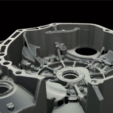
AST started by using a GOM ATOS IIe scanner from Capture3D to collect data on as many surfaces as possible on the casting. The ATOS scanner uses white light to project fringe patterns onto an object’s surface. The patterns are captured by cameras positioned on each side of the scanner’s sensor head.
It took AST about a day and a half to complete the scanning. The process was made more painstaking than usual by the need to move the 300-pound casting to capture as much surface data as possible. The casting had numerous surface imperfections picked up by the scanner, and internal surfaces under the flanges and inner holes could not be captured.
Polygonal data from the ATOS scanner was brought into Geomagic Design X, software that is used by manufacturers worldwide to transform 3D scan data into accurate models for downstream CAD, manufacturing and engineering analysis.
AST cleaned up the model in Geomagic Design X, removing holes, smoothing surfaces, and automatically filling in sections not captured by the scanner. The next step would normally be generating a NURBS surface model from the polygon model. But, the job requirements led AST to a different approach.
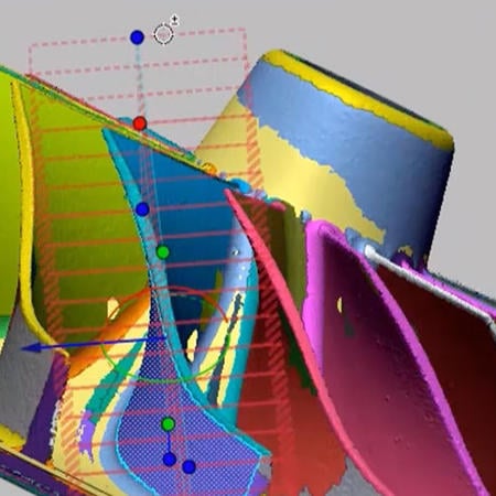
Instead of generating surfaces from polygons, AST used Geomagic Design X to automatically create a symmetry plane based on an educated guess of where it might be located. AST then cut sections from planes that were created parallel or perpendicular to the symmetry plane.
“The ability of Geomagic Design X to provide accurate symmetry planes using intervals that we defined based on offsets was critical to making our process work,” says Steve Lelinski, AST’s research engineer.
The coarsely cut sections were brought into Pro/ENGINEER for alignment and to create dimensions and features, and the original drawings were used as a conceptual reference. As the model was refined, AST shuttled back and forth between Pro/ENGINEER and Geomagic Design X. Geomagic Design X was used to cut the model into ever-smaller orthogonal slices, starting with two-inch sections and whittling down to one-eighth of an inch. As the model was refined, details were checked and revised in Pro/ENGINEER.
Ease of Editing
“The most important reason for this approach,” says Lelinski, “was that we needed a parametric model that could be edited. Also, the part had to be a combination of the scan data and the original drawing.”
A finished surface model is difficult to change, according to Lelinski, and AST needed to be able to easily and quickly revise features on the part. In fact, once the model was finished and HUB presented it to the customer, a feature needed to be moved. Because AST had created a parametric, section-based model, the change was easy to make.
“If we were working with a surfaced model,” says Lelinski, “we would have had to either start at the beginning by moving the polygons and resurfacing, or break apart the surfaces, make changes, and attempt to merge them back together. Neither of these options is quick nor easy.”
AST’s sectioning approach lent itself to a model that needs to reflect both the intent of the drawing and the actual details of the physical part. Arriving at this kind of combination model would have been difficult using the typical scan-to-surface procedure, and changes would have been more time-consuming, according to Lelinski.
“By creating the model in Pro/ENGINEER using the sections from Geomagic Design X as our guide, we were able to put features in their proper location, with the correct dimensions and thicknesses from the beginning,” he says.
The flexibility of the sectioned model also made it easy to determine draft angles for the casting model. AST used the scan data to obtain measurements at the top and bottom of surfaces, then performed a mathematical operation to calculate the angles. The angles were then adjusted when cross sections were laid into the model.
Inspection in Reverse
The final bit of AST ingenuity came about during verification of the finished model. This was done through a process that Chip Potter calls “reverse inspection.” Instead of the typical process of inspecting an as-built part against the CAD model, AST used Geomagic Control to inspect the CAD model against scan data from the tamper casting.
Color-mapped visual results automatically created by Geomagic Control made it simple to see deviations between the CAD model and the scan model. Overall, the CAD model was accurate, except for problems with an off-center bore and variable wall thickness.
After about a half-dozen iterations correcting problems, fine-tuning draft angles, determining casting shrinkage, and re-inspecting, AST arrived at an accurate model. The entire process – from scanning to processing to verification – was accomplished within the allotted two-week timeframe.
Capturing Long-Lost Design Intent
There is no good way of telling how much time AST’s process saved, simply because there was no other way to accurately reproduce the casting within a reasonable period of time. It would take hundreds of hand measurements to match the equivalent of the one-eighth-inch sections created in Geomagic Design X, and the curved surfaces of the casting would have made accurate measurements impossible. A coordinate measuring machine (CMM) wasn’t suitable for the job either since the probe wouldn’t be able to account for shifting, shrinkage, and warpage in the physical casting.
“There was no other way to do this cost-effectively since the drawings did not represent the casting as built,” says Potter. “We were given this project after others had tried and failed. Using our methods, in two weeks we were able to build a complete parametric model that captured design intent which was lost 40 years ago.”
The completed model was delivered to HUB, which imported it into SurfCAM software to make modifications such as pulling cores out, creating split lines for core boxes, and generating patterns to fit the existing casting. Tool paths were created and the model was sent to HUB’s large Johnford CNC machines for cutting. The finished casting patterns were cleaned up and lacquered, then delivered to Southern Cast before the 30-day deadline.
Keeping it Close to Home
For Don Cloeter of HUB, the project proves that skill and technology can cost-effectively provide answers to problems that might normally be considered impractical to solve or be sent offshore to be handled by a low-cost labor force.
“I was pleased with the quality of AST’s work, and my customer was satisfied with our work. I think this shows that skilled professionals using new technologies can solve difficult problems at a reasonable cost if they are given the opportunity. Our methods might appear more expensive than offshore outsourcing at first, but in the end, you’ll pay about the same or less for a better solution.”