Just how fast can a physical part without any existing CAD data be accurately recreated for real-world use?
That's what John Murray and Stewart Davis of 3D Systems set out to find. In the process, they showed that duplicating a complex physical part is a lot easier, faster and more accurate than most might expect.
"Stewart and I are both motorcycle fanatics," says Murray, senior director of global business development, motorsports, for 3D Systems. "We wanted to see just how quickly and accurately we could reproduce a free-form motorcycle fairing without any pre-existing CAD data."
Complications of a free-form fairing
A motorcycle's fairing serves much the same purpose as a car's fender - it's the skin of the bike, providing critical airflow for engine cooling and shuttling away on-coming air for better aerodynamic performance. The Ducati 996S fairing that 3D Systems (www.3dsystems.com) chose to scan also has an outlet duct to redirect radiator exhaust to the back of the bike.
"The function is also aesthetic," says Murray. "Ducati has a very unique design and takes great pride in the lines of the bike."
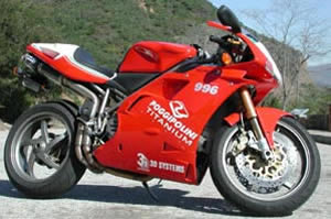
Ducati 996S motorcycle with original fairing.
The unique design of the fairing didn't lend well to creating CAD data for the part by using photographs, measurements and other 2D data. To create a digital model, Murray and Davis sought the help of Kevin Scofield, applications engineer with Geomagic (www.geomagic.com), maker of Geomagic Wrap reverse-engineering software.
"We've worked with Kevin and Geomagic before and were impressed with the capabilities," says Murray. "Our primary goal with the reverse-engineering process was to get a file we could work with without any manipulation. Based on our previous experience with Geomagic, we knew the software would meet our needs."
Streamlining the surfacing process
Murray and Davis detached the bike's original fairing and shipped it to Scofield in Geomagic's offices in Research Triangle Park, N.C. Scofield scanned the approximately two-foot by one-and-a-half-foot fairing using the Minolta Vivid 910 3D scanner. Complete scanning of the part took about 90 minutes and yielded 15 scans.
Data from the 15 individual scans were imported into Geomagic Wrap and aligned in the same coordinate space using the Partial and Global Alignment functions, where the software sorts through all of the scan data and selects the best data in overlapping regions, automatically fitting them together like a 3D puzzle. The software then generated a high-quality polygonal mesh of the fairing that was smoothed and cleaned.
Next, Scofield worked on a slot and holes that were present on the original part and the polygonal model. The holes accommodate fasteners that attach the fairing to the bike's frame. Scofield identified these holes as features in Geomagic. The software's Create Features function computes and records the location, radius and axis of each hole, and then removes them from the surface of the model. This approach enables a CAD model to have better surface quality, and the features can be added later in the CAD software as primitive geometry.
Scofield then offset the polygonal surface by 0.12 inch to create an inner surface for the model that represents the thickness of the material. "Since the fairing was relatively thin with uniform thickness, we only needed to scan the outside," he says. "Offsetting the original surface to create the back of the part was more time-efficient than scanning both sides of the original."
After processing the data in Geomagic, an IGES file, a watertight stereolithography (STL) file that represented the thickness of the fairing, and two CAD files were created. One CAD file contained the NURBS surfaces for both the inner and outer surfaces of the fairing, and the other contained the geometry data and datum locations of the holes and slots selected with the Create Features function. The CAD files were exported to PTC's Pro/ENGINEER software. A final CAD file was created by merging the two surfaces and punching out the holes and slot.
"The Create Features tool enables users to mark the size and location of holes on the model and remove them for easier surfacing," says Scofield. "Once the features and surfaces are imported into a CAD program, they are at the exact location and size as the original scanned object. The holes can even be modified since they are true CAD features."
The final models were created from 3.3 million scan data points, and the optimized STL file contained 125,000 polygons. The entire process of generating the watertight STL file, IGES file, and CAD files, including scanning the original fairing, took about four hours.
Creating a part for real-world use
Scofield sent the finished IGES, STL and CAD files to Davis, senior applications engineer with 3D Systems.
"We wanted the original IGES file for another phase of the project," says Stewart. "We were prepared to use it to create an STL file in-house, but the STL file Kevin provided was excellent and we didn't need to make any modifications."
The STL file was then imported into and oriented for build in 3D Systems' Lightyear software for the company's SLA 7000 solid imaging system. The SLA 7000 system enabled two fairings to be built simultaneously using Accura SI 40 material. The SI 40 material is a resin that withstands high temperature and breakage, allowing the parts to be used in real-world applications.
3D Systems' solid imaging process uses a laser beam to expose and solidify successive layers of a photosensitive liquid until the desired object is formed to precise specifications in epoxy or acrylic resin. The build process for both fairings took about 45 hours and they were polished for 10 hours to smooth out the surface and achieve a high-gloss shine on the clear part. According to Davis, the sanding and polishing of a finished model doesn't alter the final dimensions of the product.
After about 60 hours of work beginning with scanning the actual fairing, the polished fairing was fit onto the original bike and then tested on roads near 3D Systems' headquarters. The bike was run for about 90 minutes and reached speeds up to 95 mph.
"The reverse-engineered fairing ran well," says Murray. "There were no problems with fit or performance."
Extending the project
Davis and Murray want to expand the project by conducting pressure tests on the reverse-engineered fairings. The tests will evaluate aerodynamic performance of the part by embedding pressure tappings in the CAD file. When the file is output to and built on the SLA 7000 system, the integrated pressure tappings will give aerodynamicists a much better view of the reverse-engineered fairing's aerodynamic efficiency.
Davis and Murray also see the possibility to manufacture some of the bike's mechanical components that would be difficult to model from scratch in a CAD program.
"We have a variety of solid imaging systems that produce parts of metal, nylon and wax, not just epoxy resin," says Davis. "We can even modify existing parts and test them. Scanning an object and using Geomagic software to create a clean CAD model saves a huge chunk of time."
"The integration from scanning to physical prototype was seamless," says Murray. "Often those two worlds don't go together well. In the end, we've been able to make an end-use item and prove that reverse engineering really works."
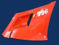
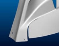
Original Ducati 996S fairing.
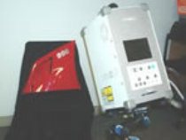
Fairing being scanned with the Minolta Vivid 910 3D scanner.
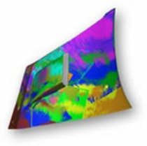
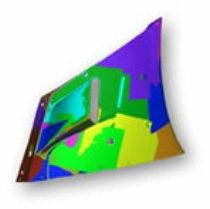
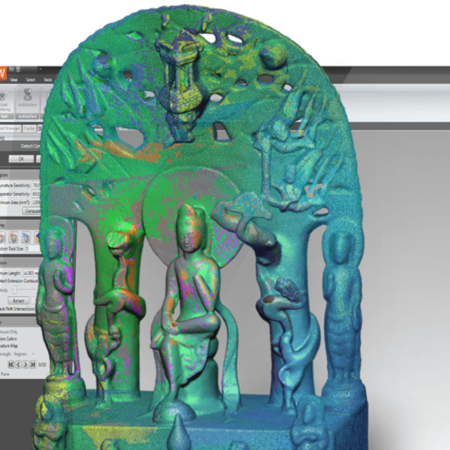
Aligned scan data for motorcycle fairing from 15 separate scans. Each color represents data from an individual scan.
Trimmed scan data for motorcycle fairing that has been aligned in Geomagic. Geomagic’s Partial and Global Alignment functions select the best data in overlapping regions.
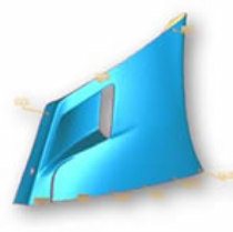
Smoothed and cleaned polygonal mesh model of motorcycle fairing. Holes and slots in the model are identified with Geomagic's Create Features function. The location, radius and axis of each hole is recorded then removed from the model’s surface for better surfacing.
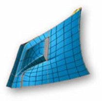
Surface model of motorcycle fairing with features removed. The original outer surface was offset by 0.12” inch in Geomagic to create an inner surface for the model.
The IGES surface files and files containing datum axes for the holes and slot were exported from Geomagic and merged in Pro/ENGINEER. Holes and slots were punched in the Pro/E CAD file using the axes’ data recorded in Geomagic.
Close-up of the holes created in the motorcycle fairing CAD files from axes data recorded in Geomagic.

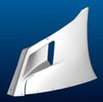
The polished reverse-engineering fairing installed on the original bike. The reverse-engineered part was built on 3D Systems’ SLA 7000 solid imaging system.
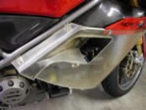
Close-up the outlet duct on the reverse-engineered fairing. The duct redirects radiator exhaust to the back of the bike.
 hero")